
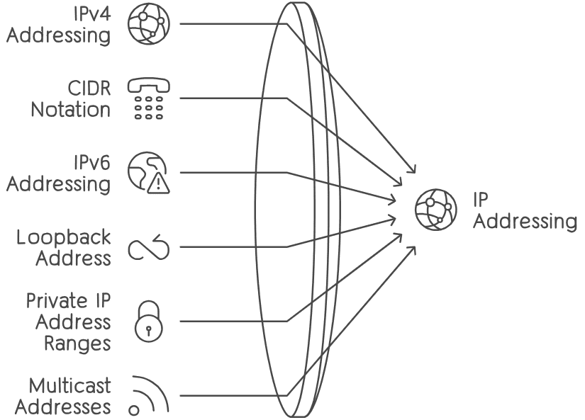
In the expansive universe of computer networking, few concepts are as foundational and omnipresent as IP addresses. Serving as unique identifiers for devices across networks, IP addresses enable seamless communication and data exchange within the digital realm. In this exhaustive guide, we will be demystifying IP addresses and embark on a thorough exploration of IP addressing, traversing the familiar terrain of IPv4 while delving into the uncharted territories of IPv6. From subnetting strategies to reserved address spaces, from network architectures to subnet calculators, we embark on a journey of discovery, leaving no stone unturned in our quest for understanding.
IPv4 Addresses
IPv4, short for Internet Protocol version 4, remains the backbone of modern networking infrastructure. With its 32-bit address space, IPv4 facilitates the allocation of unique identifiers to devices participating in computer networks worldwide.
IPv4 Addressing
At the heart of IPv4 lies its addressing scheme, which provides a unique numerical identifier to every device connected to the internet. An IPv4 address is a 32-bit number represented in dotted-decimal notation, comprising four octets separated by periods. Each octet can range from 0 to 255, allowing for approximately 4.3 billion unique addresses.
Address Classes
IPv4 addresses are divided into five classes: A, B, C, D, and E. Classes A, B, and C are used for host addressing, while Class D is reserved for multicast addressing, and Class E is reserved for experimental use. Each class has a specific range of addresses, with Class A having the largest network portion and the smallest host portion, and Class C having the opposite arrangement.
Subnetting
To manage the finite pool of IPv4 addresses more effectively, subnetting was introduced. Subnetting involves dividing a large network into smaller, more manageable subnetworks. This process allows organizations to optimize address usage and improve network efficiency by allocating addresses based on their specific requirements.
Reserved IP Addresses
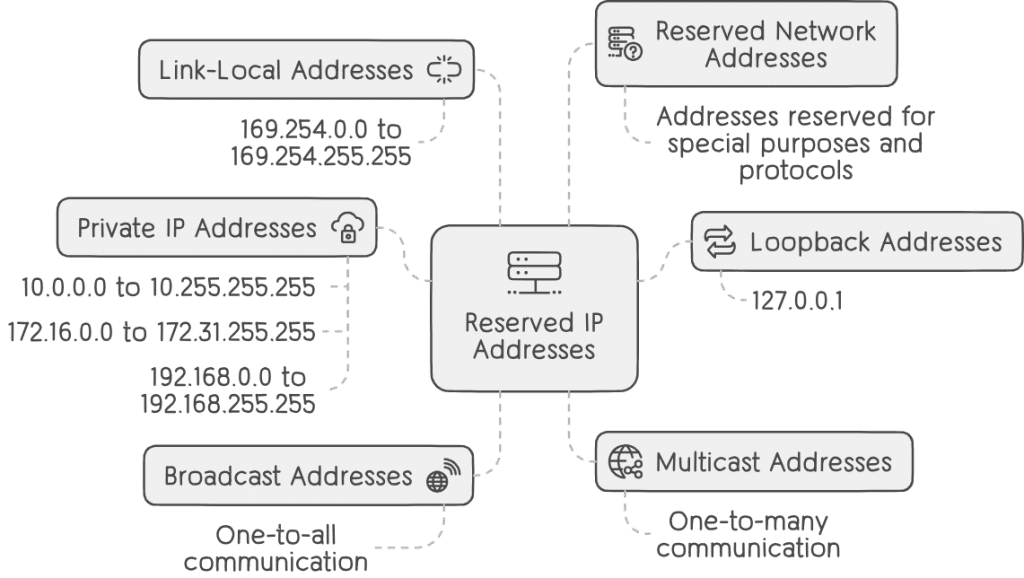
Reserved IP addresses play a crucial role in the functioning and management of computer networks, particularly in the context of IPv4 addressing. These addresses are set aside for specific purposes, ranging from private network usage to special functionalities like loopback and broadcast addressing. Understanding reserved IP addresses is essential for network administrators and engineers to effectively design, configure, and troubleshoot networks. Let’s delve into the intricacies of reserved IP addresses:
Private IP Addresses
Private IP addresses are reserved for use within private networks and are not routable over the public internet. They enable organizations to create their own internal networks while isolating them from the broader internet. The three primary ranges of private IP addresses defined in RFC 1918 are:
- 10.0.0.0 to 10.255.255.255 (10.0.0.0/8)
- 172.16.0.0 to 172.31.255.255 (172.16.0.0/12)
- 192.168.0.0 to 192.168.255.255 (192.168.0.0/16)
Private IP addresses are commonly used in home, corporate, and enterprise networks to provide internal communication and connectivity among devices without the need for public IP addresses.
Loopback Addresses
The loopback address, commonly represented as 127.0.0.1, is a reserved IP address that allows a device to send packets to itself. It is often used for diagnostic and testing purposes, allowing applications and network services running on the device to communicate with themselves. The loopback interface is essential for troubleshooting network configurations and verifying the functionality of network services.
Broadcast Addresses
Broadcast addresses are used to send data packets to all devices within a specific network segment. In IPv4 networks, the broadcast address is typically the highest address within the network’s address range. For example, in a subnet with the address range 192.168.1.0 to 192.168.1.255, the broadcast address would be 192.168.1.255. Broadcast addressing facilitates communication between devices within the same network segment and is commonly used in protocols such as ARP (Address Resolution Protocol) and DHCP (Dynamic Host Configuration Protocol).
Multicast Addresses
Multicast addresses are reserved for one-to-many communication, where a single packet is sent from one source to multiple recipients simultaneously. Unlike broadcast addresses, multicast addresses are used for specific multicast groups and applications. Multicast addressing enables efficient content distribution and collaboration across networks.
Link-Local Addresses
Link-local addresses are reserved for communication within a single network segment or link. They are automatically assigned to network interfaces when no other IP configuration is available. Link-local addresses, designated in the range 169.254.0.0 to 169.254.255.255 (169.254.0.0/16), facilitate local network communication and can be used for network troubleshooting and configuration.
Reserved Network Addresses
Beyond private, loopback, broadcast, multicast, and link-local addresses, various other IP addresses are reserved for special purposes and protocols. These include addresses reserved for documentation, future use, and specific protocols such as IPsec (Internet Protocol Security) and ICMP (Internet Control Message Protocol).
IPv4 Header
The IPv4 header is a fundamental component of the IPv4 protocol stack. It contains essential information required for routing packets across networks, including source and destination addresses, packet length, protocol version, and Time-to-Live (TTL) field.
Header Fields
- Version: Indicates the version of the IP protocol being used (IPv4 in this case).
- Header Length: Specifies the length of the header in 32-bit words.
- Type of Service (ToS): Originally designed for specifying Quality of Service (QoS) parameters, this field is now commonly used for Differentiated Services Code Point (DSCP) markings.
- Total Length: Specifies the total length of the IP packet in bytes.
- Identification, Flags, and Fragment Offset: Used for packet fragmentation and reassembly.
- Time-to-Live (TTL): Prevents packets from circulating indefinitely in the network by decrementing each time it passes through a router.
- Protocol: Identifies the protocol encapsulated in the payload (e.g., TCP, UDP).
- Header Checksum: Ensures the integrity of the header during transmission.
- Source and Destination IP Addresses: Specifies the source and destination addresses of the packet.
IPv4 Limitations
Despite its ubiquity, IPv4 faces significant limitations, chief among them being address exhaustion. The exponential growth of internet-connected devices has led to a depletion of available IPv4 addresses. To address this challenge, IPv6 was developed as the successor to IPv4, offering an immensely larger address space to accommodate the growing demands of the internet.
IP/Mask
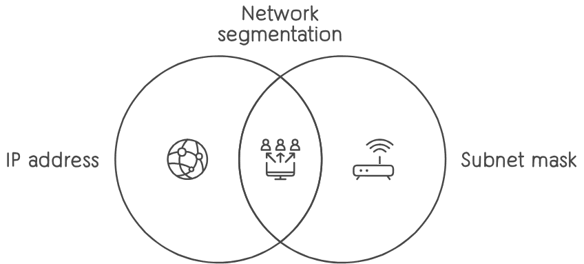
IP/Mask, also known as subnetting, is a fundamental concept in computer networking that involves combining an IP address with a subnet mask to define the network and host portions of the address. Understanding IP/mask notation is essential for network administrators and engineers to efficiently allocate and manage IP addresses within a network. Let’s explore IP/mask in more detail:
IP/Mask Notation
IP/mask notation, also known as CIDR (Classless Inter-Domain Routing) notation, is used to represent IP addresses and their associated subnet masks. It consists of an IP address followed by a slash (/) and a number, indicating the length of the network prefix. For example:
192.168.1.0/24: This notation represents an IP address (192.168.1.0) and its corresponding subnet mask (255.255.255.0). The “/24” indicates that the first 24 bits of the address are used for the network portion, leaving 8 bits for the host portion.
IP/Mask CIDR Example
CIDR notation allows for flexible and efficient allocation of IP addresses within a network. By specifying the network prefix length, CIDR notation enables networks of varying sizes to be created and managed. For example:
192.168.1.0/24: This notation represents a network with a subnet mask of 255.255.255.0, allowing for 254 usable host addresses within the subnet.
IP/Mask Host Example
IP/host notation focuses on the number of hosts available within a subnet. It specifies the number of bits allocated for host addresses, which determines the total number of usable host addresses. For example:
192.168.1.0/27: This notation indicates a subnet with 32 IP addresses, accommodating 30 usable hosts. The “/27” prefix length means that 27 bits are allocated for the network portion, leaving 5 bits for host addresses.
Benefits of Subnetting
Subnetting offers several benefits in network design and management:
- Efficient Address Allocation: Subnetting allows organizations to divide large address spaces into smaller, more manageable subnets, optimizing address usage and conserving IP addresses.
- Improved Network Performance: By segmenting networks into smaller subnets, network traffic can be localized, reducing congestion and improving overall network performance.
- Enhanced Security: Subnetting enables the implementation of network security policies at a more granular level, restricting access between different subnets and improving network security.
- Simplified Network Management: Subnetting facilitates easier network administration by organizing devices into logical groups based on their network requirements, making it easier to troubleshoot and maintain network infrastructure.
Network and Broadcast Addresses
Network and broadcast addresses are fundamental components of network addressing and play crucial roles in facilitating communication between devices within a network segment. Understanding network and broadcast addresses is essential for network administrators and engineers to configure and manage networks effectively. Let’s delve deeper into these concepts:
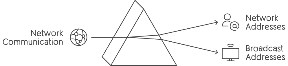
Network Address
The network address, also known as the network identifier, is the address used to identify the network to which a device belongs. It represents the beginning of a network segment and is typically assigned to the first address in the address range allocated to the network. The network address is used by devices to determine whether a packet needs to be routed within the local network or forwarded to another network.
For example, in a network with the IP address range 192.168.1.0/24, the network address is 192.168.1.0. This address identifies the network to which devices with IP addresses within the range belong.
Broadcast Address
The broadcast address is a special address used to send data packets to all devices within a specific network segment. When a device sends a packet to the broadcast address, it is received by all devices on the same network segment. This allows for the dissemination of data to multiple recipients simultaneously without the need for individual addressing.
The broadcast address is typically the highest address within the address range allocated to the network. In the example network with the IP address range 192.168.1.0/24, the broadcast address is 192.168.1.255. Any packet sent to this address will be received by all devices within the network segment.
Usage and Significance
- Address Resolution Protocol (ARP): ARP is a protocol used to map IP addresses to MAC addresses on a local network. When a device needs to determine the MAC address associated with a specific IP address, it sends an ARP request to the broadcast address. The device with the corresponding IP address responds with its MAC address.
- DHCP (Dynamic Host Configuration Protocol): DHCP is a protocol used to automatically assign IP addresses to devices on a network. DHCP servers use broadcast messages to offer IP address leases to client devices that request them.
- Network Troubleshooting: Broadcasting messages can be useful for network troubleshooting and diagnostics. For example, network administrators can use broadcast messages to detect devices on the network or to test network connectivity.
IP Examples
IP examples illustrate how IP addresses are formatted and utilized in networking scenarios, showcasing their practical applications across various contexts. Understanding IP examples helps individuals grasp the nuances of IP addressing and its role in facilitating communication between devices within networks. Let’s explore some IP examples:
IPv4 Addressing
Consider an IPv4 address of 192.168.0.1 with a subnet mask of 255.255.255.0:
- IP Address: 192.168.0.1
- Subnet Mask: 255.255.255.0
- Network Address: 192.168.0.0
- Broadcast Address: 192.168.0.255
- Usable Host Range: 192.168.0.1 to 192.168.0.254
In this example, the IP address is part of the subnet with a network address of 192.168.0.0 and a broadcast address of 192.168.0.255. The subnet mask of 255.255.255.0 indicates that the first 24 bits of the IP address represent the network portion, while the last 8 bits represent the host portion.
CIDR Notation
CIDR notation provides a concise representation of IP addresses and their associated network prefixes. For instance:
- 192.168.1.0/24: This CIDR notation represents a network with a subnet mask of 255.255.255.0, allowing for 254 usable host addresses within the subnet.
IPv6 Addressing
IPv6 addresses have a more complex structure and are represented in hexadecimal format. An example IPv6 address is 2001:0db8:85a3:0000:0000:8a2e:0370:7334.
- IPv6 addresses offer a significantly larger address space compared to IPv4, enabling the allocation of unique addresses to a vast number of devices.
Loopback Address
The loopback address, commonly represented as 127.0.0.1 in IPv4 and ::1 in IPv6, allows a device to send packets to itself for testing and diagnostic purposes. It serves as a fundamental tool for verifying network functionality on a local machine.
Private IP Address Ranges
Private IP address ranges, defined in RFC 1918, include:
- 10.0.0.0 to 10.255.255.255 (10.0.0.0/8)
- 172.16.0.0 to 172.31.255.255 (172.16.0.0/12)
- 192.168.0.0 to 192.168.255.255 (192.168.0.0/16)
These ranges are reserved for internal network use and are not routable on the public internet.
Multicast Addresses
Multicast addresses enable one-to-many communication, where a single packet is sent to multiple recipients simultaneously. An example IPv4 multicast address is 224.0.0.1, reserved for all hosts on the local network segment.
Link-Local Addresses
Link-local addresses, such as 169.254.0.0/16 in IPv4 and fe80::/10 in IPv6, are automatically assigned to network interfaces when no other IP configuration is available. They facilitate local communication within a single network segment.
Reserved IP Addresses
Reserved IP addresses include documentation addresses, future use addresses, and specific protocol addresses designated for special purposes within the IP protocol suite.
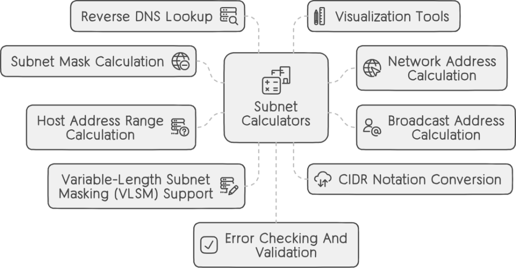
Subnet Calculators
Subnet calculators are invaluable tools used by network administrators and engineers to streamline the process of subnetting and network planning. These calculators automate the tedious calculations involved in determining subnet masks, network addresses, broadcast addresses, and available host ranges based on user input. Let’s explore the features and benefits of subnet calculators:
Subnet Mask Calculation
Subnet calculators assist in calculating the appropriate subnet mask based on the desired number of subnets and hosts per subnet. Users input the number of subnets and hosts required, and the calculator determines the optimal subnet mask to accommodate these requirements while minimizing address wastage.
Network Address Calculation
Given an IP address and subnet mask, subnet calculators determine the network address for a subnet. They perform bitwise AND operations between the IP address and subnet mask to derive the network portion of the address.
Broadcast Address Calculation
Subnet calculators compute the broadcast address for each subnet by setting all host bits in the network portion of the address to 1. This broadcast address allows devices within the subnet to communicate with each other using broadcast messages.
Host Address Range Calculation
Subnet calculators determine the range of usable host addresses within each subnet by excluding the network and broadcast addresses. This information is vital for assigning IP addresses to devices within the subnet while avoiding conflicts and optimizing address utilization.
Variable-Length Subnet Masking (VLSM) Support
Advanced subnet calculators support Variable-Length Subnet Masking (VLSM), allowing users to allocate different subnet sizes within the same network based on specific requirements. This flexibility enables efficient utilization of IP address space and facilitates network optimization.
CIDR Notation Conversion
Subnet calculators convert IP addresses and subnet masks between decimal and CIDR notation, simplifying address representation and configuration. CIDR notation provides a concise and standardized format for expressing IP address ranges and subnet masks.
Reverse DNS Lookup
Some subnet calculators offer the ability to perform reverse DNS lookup to resolve IP addresses to domain names and vice versa. This feature enhances network troubleshooting and management by providing additional context for identified IP addresses.
Visualization Tools
Advanced subnet calculators may include visualization tools such as subnet diagrams and graphical representations of network architectures. These visual aids help users visualize subnet layouts, identify address ranges, and understand network topologies more intuitively.
Error Checking and Validation
Subnet calculators validate user input to ensure consistency and accuracy in subnet calculations. They check for common errors such as invalid IP addresses, conflicting subnet configurations, and overlapping address ranges, helping prevent configuration errors and network issues.
Multiplatform Availability
Subnet calculators are available as standalone applications, web-based tools, and mobile apps, catering to the diverse needs of network professionals across different platforms and devices.
IPv6
IPv6, short for Internet Protocol version 6, represents the next evolution of the Internet Protocol and serves as a successor to IPv4. Designed to address the limitations of IPv4 and accommodate the exponential growth of internet-connected devices, IPv6 offers several significant improvements and features. Let’s explore the key aspects of IPv6:
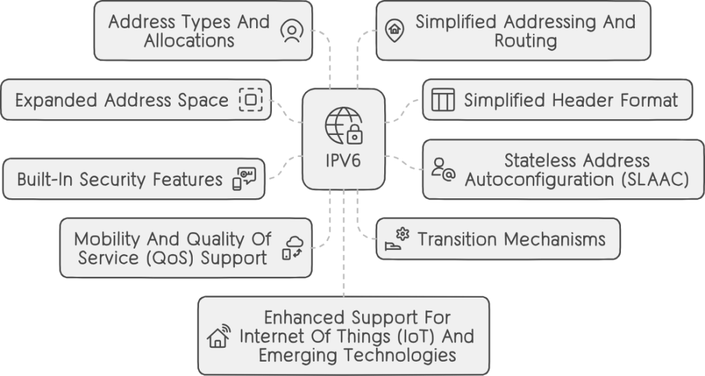
Expanded Address Space
IPv6 addresses are 128 bits in length, compared to the 32-bit addresses used in IPv4. This significantly expands the address space, allowing for approximately 3.4 × 10^38 unique addresses. The vast address space of IPv6 ensures an abundant supply of addresses to accommodate the growing number of internet-connected devices worldwide.
Simplified Header Format
IPv6 introduces a simplified header format compared to IPv4. The IPv6 header is streamlined and more efficient, reducing packet processing overhead and improving network performance. Despite its simplicity, the IPv6 header includes features such as flow labeling and extension headers for enhanced functionality.
Stateless Address Autoconfiguration (SLAAC)
IPv6 supports stateless address autoconfiguration, enabling devices to automatically generate and configure IPv6 addresses without the need for manual intervention or DHCP servers. This feature simplifies network configuration and management, particularly in dynamic and mobile environments.
Built-in Security Features
IPv6 incorporates built-in security features such as IPsec (Internet Protocol Security) as a mandatory part of the protocol suite. IPsec provides encryption, authentication, and integrity protection for IPv6 traffic, enhancing network security and privacy.
Mobility and Quality of Service (QoS) Support
IPv6 includes features to support mobility and Quality of Service (QoS) requirements in modern networks. Mobile IPv6 enables seamless mobility for devices as they move between networks, while flow labeling allows for the prioritization and differentiation of traffic based on QoS parameters.
Transition Mechanisms
IPv6 transition mechanisms facilitate the coexistence and migration from IPv4 to IPv6 networks. Techniques such as dual-stack operation, tunneling, and translation enable interoperability between IPv4 and IPv6 devices and networks during the transition period.
Address Types and Allocations
IPv6 defines several types of addresses, including unicast, multicast, and anycast addresses. Unicast addresses identify individual interfaces, multicast addresses enable one-to-many communication, and anycast addresses represent a group of devices offering the same service, with packets delivered to the nearest member of the group.
Simplified Addressing and Routing
IPv6 simplifies address assignment and routing by eliminating the need for Network Address Translation (NAT) and allowing for hierarchical addressing schemes. With its expanded address space and simplified routing mechanisms, IPv6 enables more efficient and scalable network architectures.
Enhanced Support for Internet of Things (IoT) and Emerging Technologies
IPv6 is well-suited to meet the demands of emerging technologies such as the Internet of Things (IoT), machine-to-machine communication, and sensor networks. Its large address space, low overhead, and built-in security features make IPv6 an ideal protocol for connecting and managing vast numbers of devices in diverse environments.
Global Deployment and Adoption
IPv6 adoption continues to grow globally, driven by the exhaustion of IPv4 addresses and the increasing demand for internet-connected devices. Many internet service providers, network operators, and organizations have already deployed IPv6 infrastructure and services to meet the evolving needs of the internet.
IPv6 Header
The IPv6 header is a fundamental component of the Internet Protocol version 6 (IPv6), responsible for encapsulating data packets and facilitating their transmission across IPv6 networks. The IPv6 header contains essential fields necessary for packet routing, delivery, and processing. Let’s explore the IPv6 header in detail:
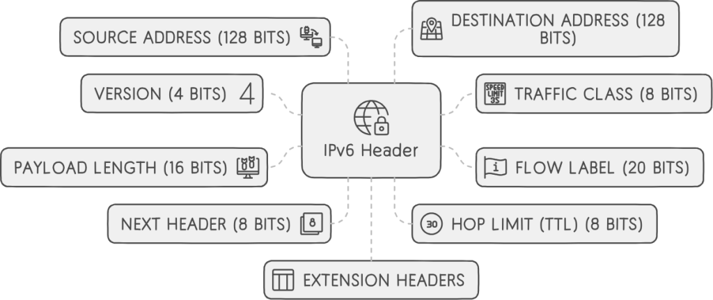
Version (4 bits)
The Version field indicates the version of the Internet Protocol used, with IPv6 being designated by the value 6. This field is fixed at 4 bits in length and is located at the beginning of the IPv6 header.
Traffic Class (8 bits)
The Traffic Class field, also known as the Differentiated Services Code Point (DSCP), is used for specifying the Quality of Service (QoS) parameters associated with the packet. It enables routers and network devices to prioritize and differentiate traffic based on predefined QoS markings.
Flow Label (20 bits)
The Flow Label field is used for identifying and categorizing packets belonging to the same flow or traffic stream. It allows for the efficient handling and processing of related packets within network devices, such as routers and switches. The Flow Label is intended to improve the performance of real-time and multimedia applications.
Payload Length (16 bits)
The Payload Length field indicates the length of the IPv6 packet’s payload, including any extension headers, measured in octets (bytes). It helps routers and network devices determine the size of the packet and allocate resources accordingly.
Next Header (8 bits)
The Next Header field identifies the type of the next header following the IPv6 header. It specifies the protocol or extension header that immediately follows the IPv6 header, allowing routers to process packets correctly based on their payload type.
Hop Limit (TTL) (8 bits)
Similar to the Time-to-Live (TTL) field in IPv4, the Hop Limit field specifies the maximum number of hops (routers) that a packet can traverse before being discarded. It prevents packets from circulating indefinitely in the network and helps prevent routing loops.
Source Address (128 bits)
The Source Address field contains the 128-bit IPv6 address of the packet’s source, uniquely identifying the sending host or device on the network. The Source Address field is located after the IPv6 header and before the Destination Address field.
Destination Address (128 bits)
The Destination Address field contains the 128-bit IPv6 address of the packet’s destination, uniquely identifying the receiving host or device on the network. The Destination Address field is located after the Source Address field in the IPv6 header.
Extension Headers
IPv6 allows for optional extension headers to be included after the main IPv6 header. These extension headers provide additional functionality and features, such as fragmentation, authentication, and security, without increasing the size of the base header. Extension headers are identified by the Next Header field in the IPv6 header.
IPv6 Forms
IPv6 addresses come in several forms, each serving specific purposes and accommodating various network configurations. Understanding the different forms of IPv6 addresses is essential for network administrators and engineers to effectively configure and manage IPv6 networks. Let’s explore the main forms of IPv6 addresses:
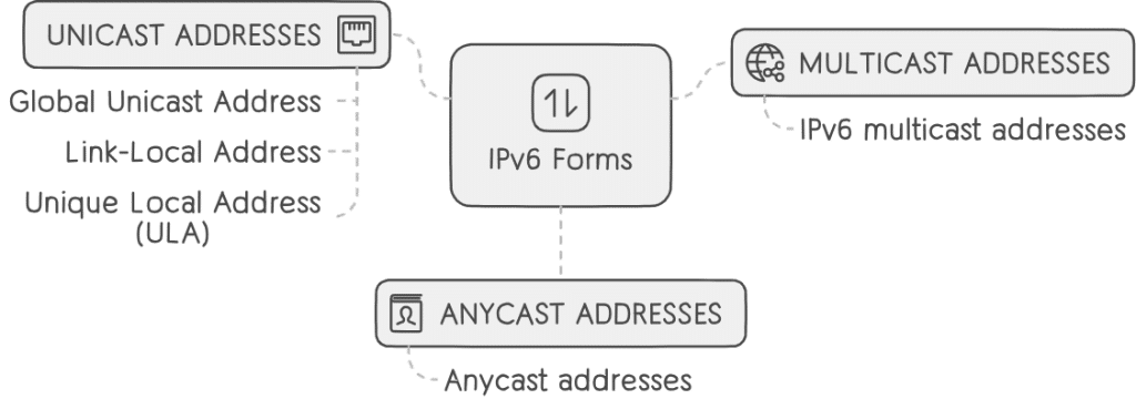
Unicast Addresses
Unicast addresses identify a single interface on an IPv6 network and facilitate communication between two endpoints. There are several types of unicast addresses in IPv6:
- Global Unicast Address: Global unicast addresses are equivalent to public IPv4 addresses and are globally routable on the IPv6 internet. They allow devices to communicate across different networks worldwide.
- Link-Local Address: Link-local addresses are used for communication within a single network segment or link. They are automatically assigned to network interfaces and do not require configuration. Link-local addresses are identified by the prefix fe80::/10.
- Unique Local Address (ULA): Unique local addresses are similar to private IPv4 addresses and are used for communication within a specific organization or site. They are not routable on the global internet and provide localized addressing for internal networks.
Multicast Addresses
Multicast addresses enable one-to-many communication, where a single packet is sent from one source to multiple recipients simultaneously. IPv6 multicast addresses are identified by the prefix ff00::/8 and allow devices to subscribe to multicast groups and receive specific types of traffic.
Anycast Addresses
Anycast addresses represent a group of devices offering the same service, with packets delivered to the nearest member of the group. Anycast addresses enable load balancing and fault tolerance by directing traffic to the closest available service instance.
Special Addresses
IPv6 defines several special addresses for specific purposes:
- Unspecified Address: The unspecified address (::) represents an unspecified or uninitialized address and is used in certain network protocols and configurations.
- Loopback Address: The loopback address (::1) allows a device to send packets to itself for diagnostic and testing purposes, similar to the IPv4 loopback address (127.0.0.1).
IPv6 Address Formats
IPv6 addresses are represented in several formats to accommodate different use cases and preferences:
- Colon-Hexadecimal Notation: IPv6 addresses are typically represented in colon-hexadecimal notation, where each 16-bit segment of the address is expressed as four hexadecimal digits separated by colons (e.g., 2001:0db8:85a3:0000:0000:8a2e:0370:7334).
- Zero Compression: Zero compression allows consecutive segments of zeros in an IPv6 address to be represented with a double colon (::) once per address to shorten the notation (e.g., 2001:db8::1).
- IPv6/IPv4 Compatibility: IPv6 addresses can include an embedded IPv4 address using the IPv4-compatible or IPv4-mapped address format (e.g., ::192.0.2.128 or ::ffff:192.0.2.128).
IPv6 Reserved Addresses
IPv6 reserved addresses refer to specific IPv6 address ranges designated for special purposes or reserved by the Internet Assigned Numbers Authority (IANA) for future use. These reserved addresses play important roles in IPv6 networking, ensuring proper functioning, compatibility, and future scalability of the protocol. Let’s explore the main categories of IPv6 reserved addresses:
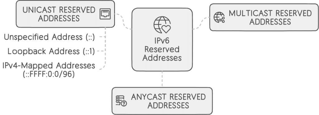
Unicast Reserved Addresses
a. Unspecified Address (::):
The unspecified address (::) serves as a placeholder or wildcard address, similar to the IPv4 address 0.0.0.0. It indicates an undefined or uninitialized address and is used in certain network protocols and configurations.
b. Loopback Address (::1):
The loopback address (::1) allows a device to send packets to itself for diagnostic and testing purposes, similar to the IPv4 loopback address (127.0.0.1). It serves as a fundamental tool for verifying network functionality on a local machine.
c. IPv4-Mapped Addresses (::FFFF:0:0/96):
IPv6 includes reserved addresses for mapping IPv4 addresses into the IPv6 address space. IPv4-mapped addresses facilitate the transition between IPv4 and IPv6 networks by allowing IPv6-aware devices to communicate with IPv4-only devices seamlessly.
Multicast Reserved Addresses
IPv6 reserves certain multicast address ranges for specific purposes, such as routing protocols, network management, and solicited-node multicast addresses used in Neighbor Discovery Protocol (NDP) for address resolution.
Anycast Reserved Addresses
Anycast addresses are not explicitly reserved in IPv6; however, specific IPv6 address ranges may be allocated for anycast addressing in certain deployments. Anycast addresses represent a group of devices offering the same service, with packets delivered to the nearest member of the group.
Documentation and Future Use
IPv6 reserves address ranges for documentation purposes and future use. These addresses are not intended for actual deployment or assignment in operational networks but are reserved to prevent conflicts and ensure compatibility with future IPv6 standards and protocols.
Special Use Addresses
IPv6 defines special-use addresses for unique purposes, such as the Teredo address range (2001::/32), which is used for IPv6 connectivity over IPv4 networks using Teredo tunneling.
Link-Local Addresses (fe80::/10)
While not explicitly reserved, the link-local address range (fe80::/10) is automatically assigned to network interfaces when no other IP configuration is available. Link-local addresses facilitate local network communication within a single network segment or link.
IPv6 Structure
The structure of IPv6 (Internet Protocol version 6) defines the format and organization of IPv6 packets, which encapsulate data for transmission across IPv6 networks. IPv6 introduces significant enhancements over IPv4, including a larger address space, streamlined header format, and support for new features and capabilities. Let’s delve into the structure of IPv6:
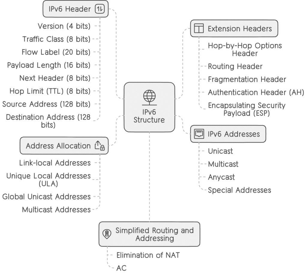
IPv6 Header
The IPv6 header is a fixed-length, 40-octet (320-bit) structure that contains essential information for packet routing, delivery, and processing. The IPv6 header consists of the following fields:
- Version (4 bits): Indicates the version of the Internet Protocol used, with IPv6 designated by the value 6.
- Traffic Class (8 bits): Specifies the Quality of Service (QoS) parameters associated with the packet, allowing routers to prioritize and differentiate traffic.
- Flow Label (20 bits): Identifies and categorizes packets belonging to the same flow or traffic stream, facilitating efficient handling within network devices.
- Payload Length (16 bits): Indicates the length of the IPv6 packet’s payload, including any extension headers, measured in octets.
- Next Header (8 bits): Identifies the type of the next header following the IPv6 header, allowing routers to process packets correctly based on their payload type.
- Hop Limit (TTL) (8 bits): Specifies the maximum number of hops (routers) that a packet can traverse before being discarded, preventing routing loops.
- Source Address (128 bits): Contains the IPv6 address of the packet’s source, uniquely identifying the sending host or device.
- Destination Address (128 bits): Contains the IPv6 address of the packet’s destination, uniquely identifying the receiving host or device.
Extension Headers
IPv6 supports optional extension headers that provide additional functionality and features beyond the base IPv6 header. Extension headers are inserted between the IPv6 header and the payload, allowing for flexible packet processing and customization. Some common extension headers include:
- Hop-by-Hop Options Header: Carries optional information that must be examined by every node along the packet’s path.
- Routing Header: Specifies the route that the packet should follow through the network, enabling source routing and explicit path selection.
- Fragmentation Header: Facilitates packet fragmentation and reassembly, allowing large packets to traverse networks with smaller Maximum Transmission Units (MTUs).
- Authentication Header (AH): Provides integrity and authentication protection for the packet, ensuring data integrity and origin authentication.
- Encapsulating Security Payload (ESP): Offers confidentiality, integrity, and authentication services for the packet’s payload, securing data transmission over the network.
IPv6 Addresses
IPv6 addresses are 128 bits in length and are expressed in hexadecimal notation. IPv6 addresses are assigned to network interfaces and serve as unique identifiers for devices on IPv6 networks. IPv6 addresses can be categorized into various types, including unicast, multicast, anycast, and special addresses.
Address Allocation
IPv6 introduces new address allocation mechanisms and address types, including link-local addresses, unique local addresses (ULA), global unicast addresses, and multicast addresses. These address types facilitate efficient and scalable address assignment in IPv6 networks.
Simplified Routing and Addressing
IPv6 simplifies routing and addressing by eliminating the need for Network Address Translation (NAT) and introducing hierarchical addressing schemes. With its larger address space and streamlined routing mechanisms, IPv6 enables more efficient and scalable network architectures.
IPv6 Scope
In IPv6, “scope” refers to the scope of an IPv6 address or a communication session, indicating the visibility and reachability of the address or session within a network or across networks. IPv6 defines several scopes, each with its own level of visibility and applicability. Understanding IPv6 scope is crucial for network administrators and engineers to properly configure and manage IPv6 networks. Let’s explore the different scopes in IPv6:
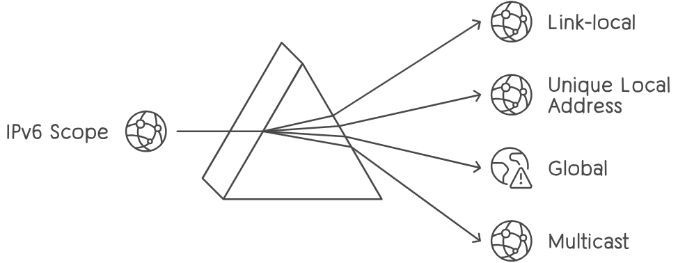
Link-Local Scope
- Definition: Link-local addresses have the smallest scope and are only valid within the local network segment or link. They are automatically assigned to network interfaces and facilitate communication between devices within the same network segment.
- Address Range: Link-local addresses are identified by the fe80::/10 prefix.
- Usage: Link-local addresses are primarily used for neighbor discovery, address resolution, and communication between devices on the same local network segment.
Unique Local Addresses (ULA) Scope
- Definition: Unique Local Addresses (ULA) are similar to IPv4 private addresses and are intended for communication within a specific organization or site. They provide localized addressing and ensure network isolation from the global internet.
- Address Range: Unique Local Addresses are identified by the fc00::/7 prefix, with a specific bit pattern reserved for Local IPv6 Unicast Addresses (L) and a Global ID portion used for uniqueness within the organization.
- Usage: Unique Local Addresses are used for internal communication, private networks, and addressing requirements within an organization, offering flexibility and independence from global address allocation.
Global Scope
- Definition: Global scope addresses have the widest reach and are globally routable on the IPv6 internet. They allow devices to communicate across different networks and geographic regions worldwide.
- Address Range: Global scope addresses are typically assigned from the globally routable address space, ensuring uniqueness and global reachability.
- Usage: Global scope addresses are used for public-facing services, internet communication, and connectivity between devices and networks worldwide.
Multicast Scope
- Definition: Multicast addresses have a scope that defines the reachability and distribution of multicast traffic within a network or across networks.
- Address Range: Multicast addresses are identified by the ff00::/8 prefix, with specific bits indicating the multicast scope.
- Usage: Multicast addresses enable one-to-many communication, where a single packet is sent from one source to multiple recipients simultaneously. Multicast scope defines the visibility and distribution of multicast traffic within the network
In IPv6, “scope” refers to the scope of an IPv6 address or a communication session, indicating the visibility and reachability of the address or session within a network or across networks. IPv6 defines several scopes, each with its own level of visibility and applicability. Understanding IPv6 scope is crucial for network administrators and engineers to properly configure and manage IPv6 networks. Let’s explore the different scopes in IPv6:
Link-Local Scope
- Definition: Link-local addresses have the smallest scope and are only valid within the local network segment or link. They are automatically assigned to network interfaces and facilitate communication between devices within the same network segment.
- Address Range: Link-local addresses are identified by the fe80::/10 prefix.
- Usage: Link-local addresses are primarily used for neighbor discovery, address resolution, and communication between devices on the same local network segment.
Unique Local Address (ULA) Scope
- Definition: Unique Local Addresses (ULA) are similar to IPv4 private addresses and are intended for communication within a specific organization or site. They provide localized addressing and ensure network isolation from the global internet.
- Address Range: Unique Local Addresses are identified by the fc00::/7 prefix, with a specific bit pattern reserved for Local IPv6 Unicast Addresses (L) and a Global ID portion used for uniqueness within the organization.
- Usage: Unique Local Addresses are used for internal communication, private networks, and addressing requirements within an organization, offering flexibility and independence from global address allocation.
Global Scope
- Definition: Global scope addresses have the widest reach and are globally routable on the IPv6 internet. They allow devices to communicate across different networks and geographic regions worldwide.
- Address Range: Global scope addresses are typically assigned from the globally routable address space, ensuring uniqueness and global reachability.
- Usage: Global scope addresses are used for public-facing services, internet communication, and connectivity between devices and networks worldwide.
Multicast Scope
- Definition: Multicast addresses have a scope that defines the reachability and distribution of multicast traffic within a network or across networks.
- Address Range: Multicast addresses are identified by the ff00::/8 prefix, with specific bits indicating the multicast scope.
- Usage: Multicast addresses enable one-to-many communication, where a single packet is sent from one source to multiple recipients simultaneously. Multicast scope defines the visibility and distribution of multicast traffic within the network
IPv6 Translation
IPv6 translation refers to the process of facilitating communication and interoperability between IPv6 and IPv4 networks by converting IPv6 packets to IPv4 packets and vice versa. As the transition from IPv4 to IPv6 continues, IPv6 translation mechanisms play a crucial role in enabling communication between devices and networks that use different versions of the Internet Protocol. There are several IPv6 translation techniques designed to address the challenges of IPv6 adoption and ensure seamless connectivity across heterogeneous networks:
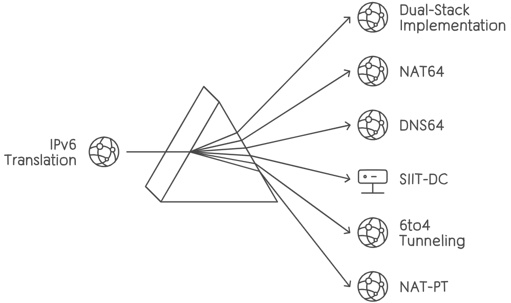
Dual-Stack Implementation
Dual-stack implementation involves running both IPv4 and IPv6 protocols simultaneously on network devices, allowing them to communicate with both IPv4 and IPv6 hosts and networks. Dual-stack devices maintain separate IPv4 and IPv6 protocol stacks, enabling transparent communication and interoperability between IPv4 and IPv6 networks without the need for translation.
NAT64 (Network Address Translation 64)
NAT64 is a translation mechanism that enables communication between IPv6-only and IPv4-only devices and networks. In NAT64, IPv6 packets are translated to IPv4 packets and vice versa at the network boundary using a combination of NAT64 and DNS64 mechanisms. NAT64 allows IPv6-only hosts to access IPv4-only resources and services on the internet and vice versa.
DNS64 (DNS to IPv6)
DNS64 is a mechanism used in conjunction with NAT64 to provide IPv6-only hosts with access to IPv4-only resources and services on the internet. DNS64 intercepts DNS queries from IPv6-only hosts and synthesizes AAAA (IPv6) records for IPv4-only domain names by mapping IPv4 addresses to IPv6 addresses. DNS64 ensures seamless connectivity between IPv6-only and IPv4-only networks by enabling transparent address resolution and translation.
SIIT-DC (Stateless IP/ICMP Translation for IPv6 Data Center)
SIIT-DC is a translation mechanism designed specifically for IPv6 data center environments. It enables communication between IPv6 and IPv4 hosts within the data center by translating IPv6 packets to IPv4 packets and vice versa. SIIT-DC operates in a stateless manner, facilitating efficient and scalable translation of IP and ICMP traffic between IPv6 and IPv4 networks.
6to4 Tunneling
6to4 tunneling is a mechanism that enables IPv6 traffic to traverse IPv4 networks by encapsulating IPv6 packets within IPv4 packets for transmission. 6to4 tunneling establishes tunnels between 6to4 relay routers, allowing IPv6 packets to be routed over IPv4 networks using automatic tunneling mechanisms. 6to4 tunneling facilitates IPv6 connectivity over existing IPv4 infrastructure and enables gradual IPv6 adoption and deployment.
NAT-PT (Network Address Translation – Protocol Translation)
NAT-PT is a translation mechanism that provides protocol-level translation between IPv6 and IPv4 networks, allowing IPv6-only and IPv4-only hosts to communicate with each other using different transport protocols. NAT-PT translates IPv6 packets to IPv4 packets and vice versa while preserving transport layer protocols and session state information. However, NAT-PT has been deprecated in favor of other translation mechanisms due to its complexity and limitations.
IPv6 Subnets
IPv6 subnets refer to the subdivision of an IPv6 network into smaller, more manageable segments known as subnetworks or subnets. Subnetting allows network administrators to efficiently allocate and organize IPv6 addresses, optimize network performance, and enhance security by segmenting traffic and controlling network access. Understanding IPv6 subnets is essential for designing, configuring, and managing IPv6 networks effectively. Let’s explore the key aspects of IPv6 subnets:
Address Space in IPv6
IPv6 addresses are 128 bits in length, providing a vast address space capable of accommodating a virtually unlimited number of devices and networks. The abundance of IPv6 addresses allows for flexible and efficient subnetting strategies to meet diverse networking requirements.
Subnet Prefix Length
In IPv6, subnetting is expressed using prefix notation, where the subnet prefix length indicates the number of bits used to identify the network portion of the IPv6 address. The remaining bits are used to identify individual hosts within the subnet. Common subnet prefix lengths in IPv6 include /64, /56, and /48, although other prefix lengths are also possible.
IPv6 Subnetting Benefits
- Address Conservation: Subnetting enables the efficient allocation of IPv6 addresses by dividing the address space into smaller, more manageable segments. This helps conserve address space and ensures optimal utilization of available IP addresses.
- Traffic Isolation and Management: Subnetting allows network administrators to isolate traffic within specific subnets, improving network performance, reducing broadcast traffic, and enhancing security by implementing access control policies at the subnet level.
- Improved Scalability: By breaking down a large IPv6 network into smaller subnets, organizations can scale their networks more effectively, accommodate growth, and adapt to changing business requirements without compromising performance or manageability.
IPv6 Subnetting
IPv6 subnetting is the process of dividing an IPv6 address space into smaller, more manageable segments called subnets. Subnetting enables efficient allocation of IPv6 addresses, organization of network resources, and optimization of network performance. Understanding IPv6 subnetting is crucial for network administrators to design and manage IPv6 networks effectively. Here’s a breakdown of IPv6 subnetting:
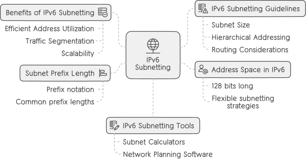
Address Space in IPv6
IPv6 addresses are 128 bits long, providing an exponentially larger address space compared to IPv4. This vast address space allows for flexible subnetting strategies without the concerns of address exhaustion.
Subnet Prefix Length
- IPv6 subnetting is defined using prefix notation, where the subnet prefix length determines the number of bits used to identify the network portion of the IPv6 address. The remaining bits are used for host addressing within the subnet.
- Common prefix lengths for IPv6 subnets include /64, /56, and /48, but other prefix lengths are also possible depending on network requirements and best practices.
Benefits of IPv6 Subnetting
- Efficient Address Utilization: Subnetting enables the efficient allocation of IPv6 addresses by breaking down the address space into smaller, more manageable segments. This helps avoid address wastage and ensures optimal utilization of available addresses.
- Traffic Segmentation: Subnets allow for the segmentation of network traffic, reducing broadcast domains and improving network performance. Segmenting traffic also enhances security by implementing access control policies at the subnet level.
- Scalability: IPv6 subnetting supports network scalability by allowing organizations to allocate addresses and resources in a structured manner. It facilitates network expansion and adaptation to changing requirements without significant redesign.
IPv6 Subnetting Guidelines
- Subnet Size: Consider the number of hosts and networks required within each subnet when determining the subnet size and prefix length. A /64 subnet is the standard recommendation for individual LAN segments due to IPv6’s auto-configuration mechanisms.
- Hierarchical Addressing: Use hierarchical addressing schemes to organize subnets based on geographic locations, departments, or functional areas within the organization. This simplifies network management and enhances scalability.
- Routing Considerations: Ensure that subnet boundaries align with routing boundaries to facilitate efficient routing and minimize routing table complexity. Subnetting should align with organizational and administrative boundaries to support logical network segmentation and routing policies.
IPv6 Subnetting Tools
- Subnet Calculators: Subnet calculators and online tools assist network administrators in calculating IPv6 subnet addresses, prefix lengths, and address ranges based on specific subnetting requirements.
- Network Planning Software: Network planning and design software provide advanced features for modeling and simulating IPv6 networks, including subnetting, address assignment, and traffic analysis.IPv6 Subnetting: Strategies for Address Allocation Optimization
Conclusion
In conclusion, IP addressing serves as the cornerstone of modern networking, facilitating communication and connectivity across the global internet. By comprehending the principles of IPv4 and IPv6 addressing, along with concepts such as subnetting and reserved address spaces, network professionals can design and manage robust and scalable network infrastructures. Through continuous exploration and adaptation, we can navigate the evolving landscape of IP addressing, ensuring the seamless operation of networks in an increasingly interconnected world.