Ethernet is a widely used networking technology that enables communication between devices within a local area network (LAN). It operates at the Data Link Layer of the OSI model. Let’s have an in-depth breakdown by decoding ethernet:
Ethernet Frame Format
Ethernet frames serve as the vehicle for data transmission across networks, encapsulating information in a structured format. The basic frame format for Ethernet, as defined in the IEEE 802.3 standard, consists of several fields:
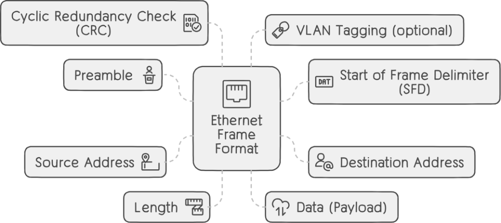
- Preamble:
- A 7-byte pattern of alternating 0s and 1s.
- Establishes bit synchronization between sender and receiver.
- Not strictly necessary in high-speed Ethernet but historically used to account for signal delays.
- Indicates the start of the frame.
- Start of Frame Delimiter (SFD):
- A 1-byte field always set to
10101011. - Marks the beginning of the destination address.
- Serves as the last chance for synchronization.
- A 1-byte field always set to
- Destination Address:
- A 6-byte field containing the MAC address of the intended recipient.
- Source Address:
- Another 6-byte field with the MAC address of the sender.
- Always an individual address (unicast), with the least significant bit of the first byte set to 0.
- Length:
- A 2-byte field indicating the entire frame’s length.
- Can hold values from 0 to 65534 (but limited to 1500 bytes due to Ethernet constraints).
- Data (Payload):
- The actual data being transmitted.
- Can be as long as 1500 bytes.
- If using the Internet Protocol (IP) over Ethernet, both IP header and data reside here.
- Padding with 0s occurs if the data length is less than the minimum (46 bytes).
- Cyclic Redundancy Check (CRC):
- A 4-byte field containing a 32-bit hash code generated over the destination address, source address, length, and data.
- Used for error detection.
- VLAN Tagging (optional):
- A 4-byte field inserted after the source address and before the EtherType field.
- Allows logical separation of a physical network into multiple virtual networks (VLANs) with unique VLAN IDs.
| Field | Size (Bytes) | Description |
|---|---|---|
| Preamble | 7 | A pattern of alternating 0s and 1s (10101010…) that synchronizes the clocks of sender and receiver. |
| Start Frame Delimiter | 1 | Marks the end of the preamble and the start of the frame header. |
| Destination MAC | 6 | MAC address of the device intended to receive the frame. |
| Source MAC | 6 | MAC address of the device sending the frame. |
| 802.1Q tag (optional) | 4 | Used to implement VLANs and indicate the quality of service (QoS) for the frame. |
| EtherType/Length | 2 | Indicates the type of protocol carried in the data field or the length of the data field. |
| Data | 46-1500 | The actual payload of the frame, such as an IP packet or an ARP request. |
| Frame Check Sequence | 4 | A CRC value calculated over the previous fields of the frame to detect transmission errors. |
MAC Addresses (Media Access Control)
MAC addresses serve as the unique identifiers of network interfaces, facilitating the delivery of frames to their intended destinations. Let’s explore the intricacies of MAC addresses:
- Every Ethernet frame contains two addresses: source and destination.
- The source address identifies the device that generated the frame, while the destination address represents the intended recipient.
- Also known as hardware address, physical address, burned-in address, universal address, or simply MAC address.
- MAC addresses are essential for delivering frames from one Ethernet NIC to another on the same LAN.
- MAC addresses consist of 48 bits, organized into six groups of two hexadecimal digits.
- The first half (24 bits) represents the organizationally unique identifier (OUI), assigned to manufacturers by the IEEE.
- The second half (24 bits) serves as the device identifier within the manufacturer’s domain.
- Consider the MAC address: 00:1A:2B:3C:4D:5E. The first 24 bits (00:1A:2B) denote the OUI, while the remaining 24 bits (3C:4D:5E) represent the device identifier.
Communication Mechanisms
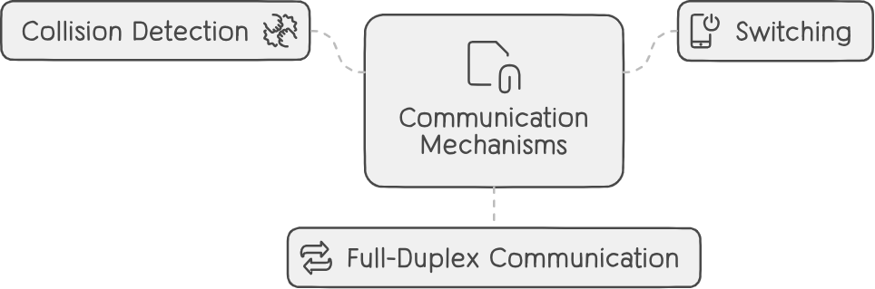
- Collision Detection:
- In shared Ethernet (e.g., 10BASE-T), devices listen for collisions during transmission.
- If a collision occurs, devices back off and retry.
- Carrier Sense Multiple Access with Collision Detection (CSMA/CD) governs this process.
- Switching:
- Ethernet switches learn MAC addresses by observing frames.
- Switches maintain a MAC address table (CAM table) to forward frames only to the relevant port.
- Switching reduces collisions and improves network efficiency.
- Full-Duplex Communication:
- Modern Ethernet allows simultaneous transmission and reception (full-duplex mode).
- No collisions occur in full-duplex mode.
- Ideal for point-to-point connections.
Examples and Calculations
Let’s illustrate with an example:
Suppose we have the following details for an Ethernet frame:
- Destination MAC address:
00:1A:2B:3C:4D:5E - Source MAC address:
08:00:27:AB:CD:EF - Data length: 1200 bytes
Frame Length Calculation
First, let’s calculate the total frame length:
- Header length (fixed fields): Preamble (7 bytes) + SFD (1 byte) + Destination address (6 bytes) + Source address (6 bytes) + Length (2 bytes) + CRC (4 bytes) = 26 bytes.
- Data length: 1200 bytes.
Total frame length = Header length + Data length = 26 + 1200 = 1226 bytes.
CRC Calculation
- Data Preparation:
- Concatenate the destination address, source address, and length fields (excluding the CRC field).
- In our example:
- Destination address:
00:1A:2B:3C:4D:5E - Source address:
08:00:27:AB:CD:EF - Length: 1200 (hexadecimal: 0x4BE)
- Destination address:
00:1A:2B:3C:4D:5E 08:00:27:AB:CD:EF 0x4BE - CRC Algorithm:
- We’ll use a polynomial division algorithm.
- The divisor (generator polynomial) is typically
0x04C11DB7. - Perform binary division (XOR operation) to find the remainder.
- Binary Representation:
- Convert the concatenated data to binary:
00:1A:2B:3C:4D:5E 08:00:27:AB:CD:EF 0x4BEbecomes a long binary string.
- Append 32 zeros (for the CRC field).
- Convert the concatenated data to binary:
- Division Process:
- Divide the binary string by the generator polynomial.
- Calculate the remainder (32 bits).
- CRC Field:
- The remainder obtained is the CRC value.
- Convert it back to hexadecimal: e.g.,
0x12345678.
Frame Assembly
Now assemble the complete Ethernet frame:
- Destination address:
00:1A:2B:3C:4D:5E - Source address:
08:00:27:AB:CD:EF - Length: 1200 (hex: 0x4BE)
- Data (payload): Actual data being transmitted
- CRC: Calculated CRC value (e.g.,
0x12345678)
Verification at Receiver
- The receiver performs the same CRC calculation on the received frame.
- If the calculated CRC matches the received CRC, the frame is error-free.
- If not, an error occurred during transmission.
Remember, Ethernet continues to evolve, adapting to higher speeds and new technologies. Through a comprehensive examination of Ethernet’s frame structure, MAC addresses, and communication mechanisms, we’ve unraveled the complexities underlying its operation.