
Today, we’re diving deep into a locked-down AT&T LTE router. AT&T doesn’t want users to be able to configure and control this device. By the end of this guide, we’ll take control and empower users to manage their devices freely. This tutorial will take you through each step in meticulous detail, covering everything from hardware exploration to software manipulation. Whether you’re a seasoned hacker or a curious novice, you’ll find valuable insights here.
The Problem
I found this device in an e-waste bin, but it’s clear that many AT&T business customers are frustrated. They can’t log into the web interface to change wireless settings on a router they purchased. AT&T’s support suggests the Wi-Fi credentials are on the back of the router, but these are not the login credentials for the router’s administrative interface. Normally, owning a router means having the ability to log in and make changes, but AT&T’s specific firmware prevents this.
The router itself is a Data Remote product, modified with custom firmware by AT&T to lock users out of advanced settings. Our goal is to regain access by figuring out the system’s login credentials.

Exploring the Hardware
Opening the Device
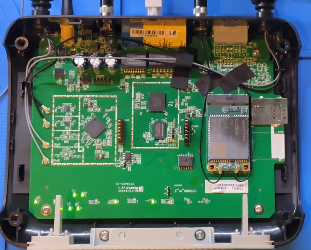
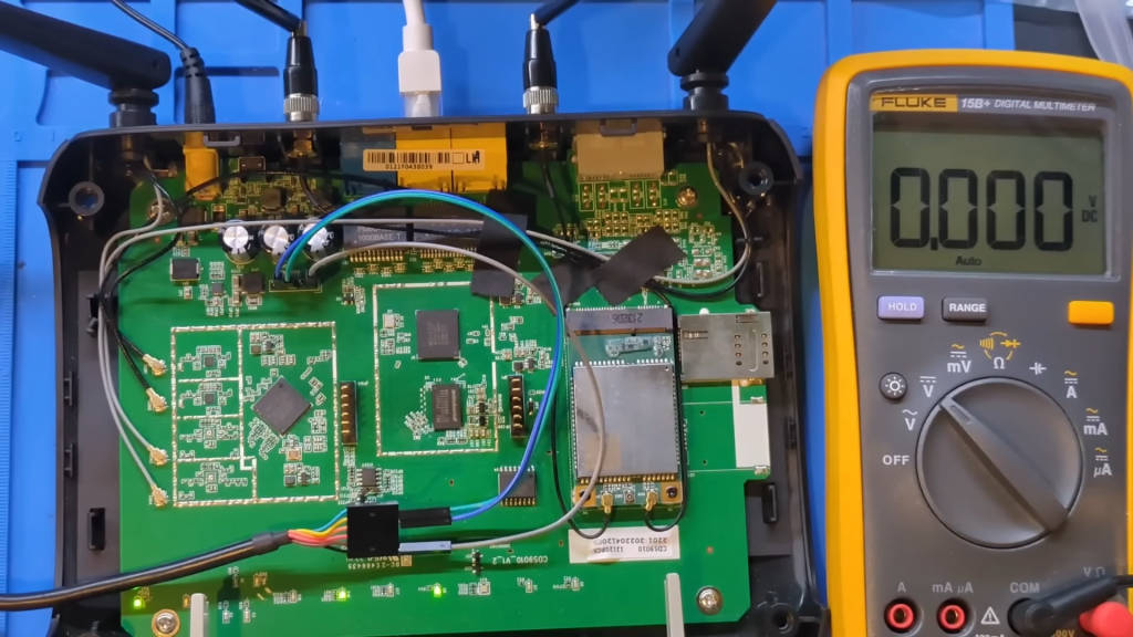
Let’s begin by opening up the router and examining the internal components. To do this, we need a set of screwdrivers and possibly some plastic prying tools to avoid damaging the casing. Once opened, we can identify the main components:
- CPU: The central processing unit of the router, responsible for executing instructions.
- DRAM: The dynamic random-access memory, which is volatile and used for temporary storage while the router is operating.
- Flash Chip: Non-volatile memory that stores the firmware and settings.
Unlike standard Wi-Fi routers, this device includes a cellular modem and a SIM card slot, enabling internet access via LTE. It also has POTS (Plain Old Telephone Service) connections, though these are likely unused in the AT&T configuration, which focuses on LTE.
Our primary focus will be to gain access to the web interface, ignoring the LTE portion for now. My eyes are drawn to a set of five pins on the board, likely a UART (Universal Asynchronous Receiver-Transmitter) connection.
Identifying the UART Pins
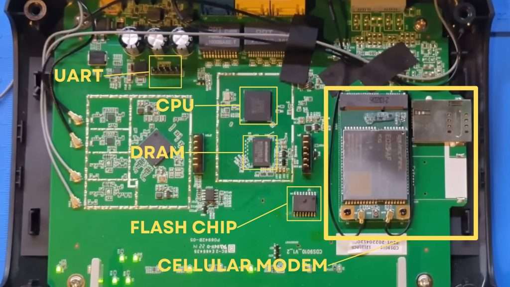
To identify the UART pins, we’ll use a multimeter. The UART interface typically consists of four or five pins:
- GND (Ground)
- VCC (Power)
- TX (Transmit)
- RX (Receive)
- CTS/RTS (Clear to Send/Ready to Send) – optional
First, we’ll find the ground pin by checking continuity with shielded components, which are always grounded. I discover that the leftmost and rightmost pins are ground. Next, I switch to voltage mode to identify the transmit (TX) and receive (RX) pins. By probing the middle three pins while powering the device, I find that the middle pin fluctuates between 0 and 3.3 volts, indicating it is the transmit pin. The pin to its left is the receive pin.
Connecting to the UART
Using a standard UART USB cable, I connect ground to the rightmost pin, receive to the middle pin (board’s TX), and transmit to the left pin (board’s RX). The connections are as follows:
- GND (Ground): Rightmost pin.
- RX (Receive): Middle pin (board’s TX).
- TX (Transmit): Left pin (board’s RX).
Setting Up the Terminal Program
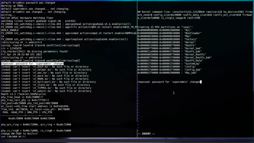
With the hardware setup complete, it’s time to interact with the device via a terminal program. We’ll use picocom, a terminal emulation program suitable for serial communication. The command to initiate the connection is:
picocom -b 115200 /dev/ttyUSB0Here, -b 115200 specifies the baud rate (115200 bits per second), and /dev/ttyUSB0 is the device file for the UART USB cable on a Linux system. The baud rate might vary depending on the device, but 115200 is a common default for many embedded systems.
Booting the Device
Upon booting, the device outputs a stream of information to the terminal. This output is crucial for understanding how the device operates. Key points include:
- Boot Command Options: Often displayed at the beginning, allowing us to interrupt the boot process.
- Kernel Command Line: Shows parameters passed to the Linux kernel during boot.
- Partition Table: Displays start and end addresses of flash partitions.

The output mentions changing the password for “super admin,” hinting at a possible username. However, no login prompt appears, suggesting the need to explore the bootloader further.
Entering the Bootloader
Interrupting the Boot Process
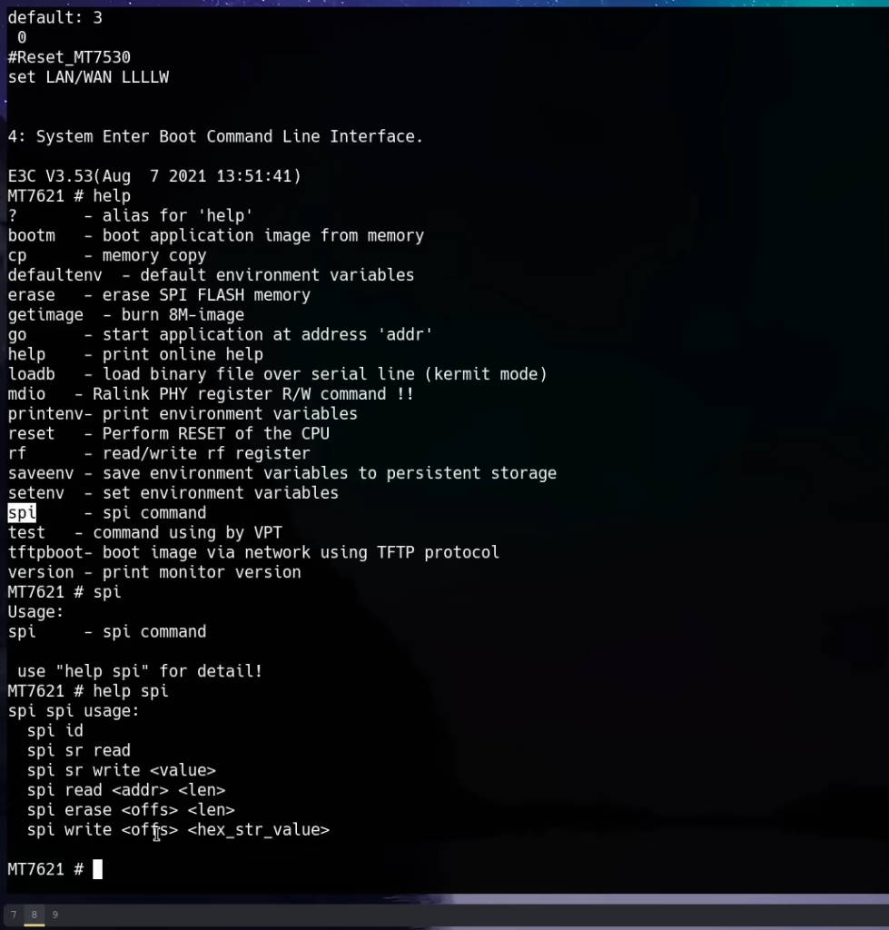
To enter the bootloader, reboot the device and press the indicated key (often ‘4’ or another number) during the boot sequence. This interrupts the boot process and provides access to the U-Boot bootloader. U-Boot is an open-source bootloader commonly used in embedded systems. It allows us to execute commands to interact with the hardware at a low level.
Exploring U-Boot Commands
Once in the U-Boot prompt, we can explore the available commands by typing help:
helpThis lists all commands supported by the bootloader. The spi command stands out, indicating the ability to interact with the flash memory.
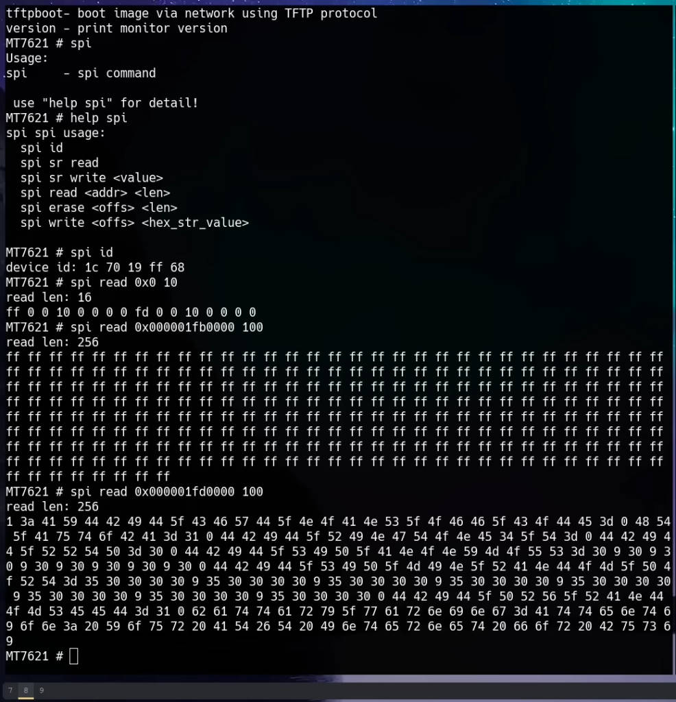
Reading Flash Memory
Understanding Flash Memory Layout
Flash memory on embedded devices is often divided into partitions, each serving different purposes (e.g., bootloader, kernel, root filesystem, configuration data). Understanding the layout is crucial for extracting relevant data. The partition table output during boot provides this information, showing start and end addresses.
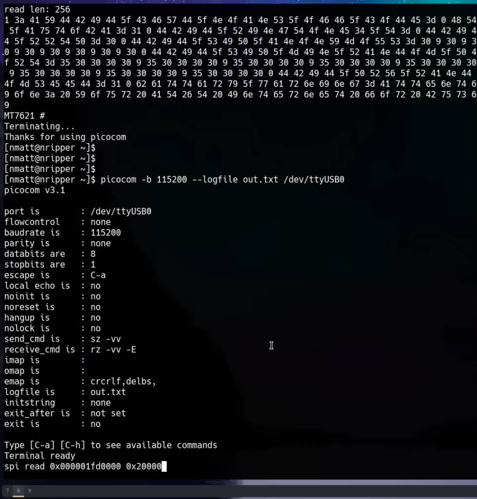
Using the spi read Command
To read the flash memory, we use the spi read command. First, we test it with small reads to confirm it works, then proceed to read the entire “config_back” partition, which appears to contain interesting data. The partition’s start and end addresses are used to calculate the length in hexadecimal.
For example, if the “config_back” partition starts at 0x1F00000 and ends at 0x2100000, the length is:
spi read 0x1F00000 0x200000The command reads data from the specified address range and outputs it to the terminal.
Extracting and Parsing Data
Capturing UART Output
To capture the output, redirect it to a file. In picocom, use the logging feature:
picocom -b 115200 /dev/ttyUSB0 -lThis logs all terminal output to a file for further analysis.
Converting Hex Dump to Binary
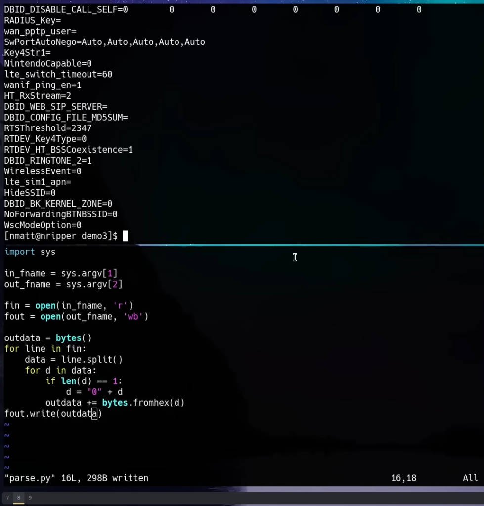
Using a text editor, prepare a Python script to parse the UART output, converting it from hex dump to binary format. The script processes the file line by line, ensuring correct byte formatting.
Here is the Python script:
pythonCopy codeimport sys

def main():
    if len(sys.argv) != 3:
        print("Usage: python hex_to_bin.py <input_hex_file> <output_bin_file>")
        return

    in_fname = sys.argv[1]
    out_fname = sys.argv[2]

    with open(in_fname, 'r') as f_in, open(out_fname, 'wb') as f_out:
        for line in f_in:
            data = line.strip().split()
            for d in data:
                if len(d) == 1:
                    d = '0' + d
                f_out.write(bytes.fromhex(d))

if __name__ == '__main__':
    main()
Save the script as hex_to_bin.py and run it with the captured UART output file and a desired output file name:
python hex_to_bin.py uart_output.txt out.binThis script reads the hex values from the captured output and writes the corresponding binary data to out.bin.
Analyzing Binary Data
Using the strings Command
To search for readable text within the binary file, use the strings command. This command scans binary files for ASCII text strings, which can reveal useful information such as usernames and passwords:
strings out.bin | grep -i adminThis command filters the output to show lines containing the term “admin”, case insensitive.
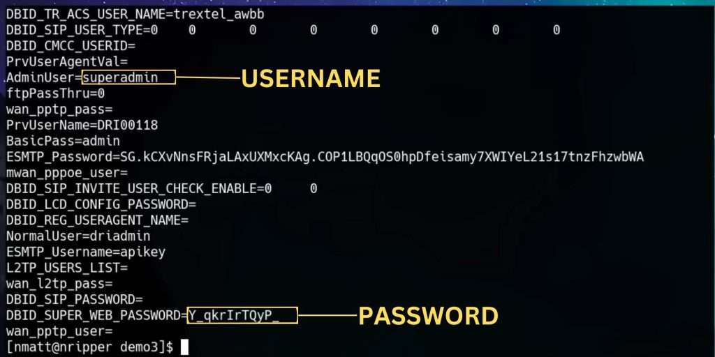
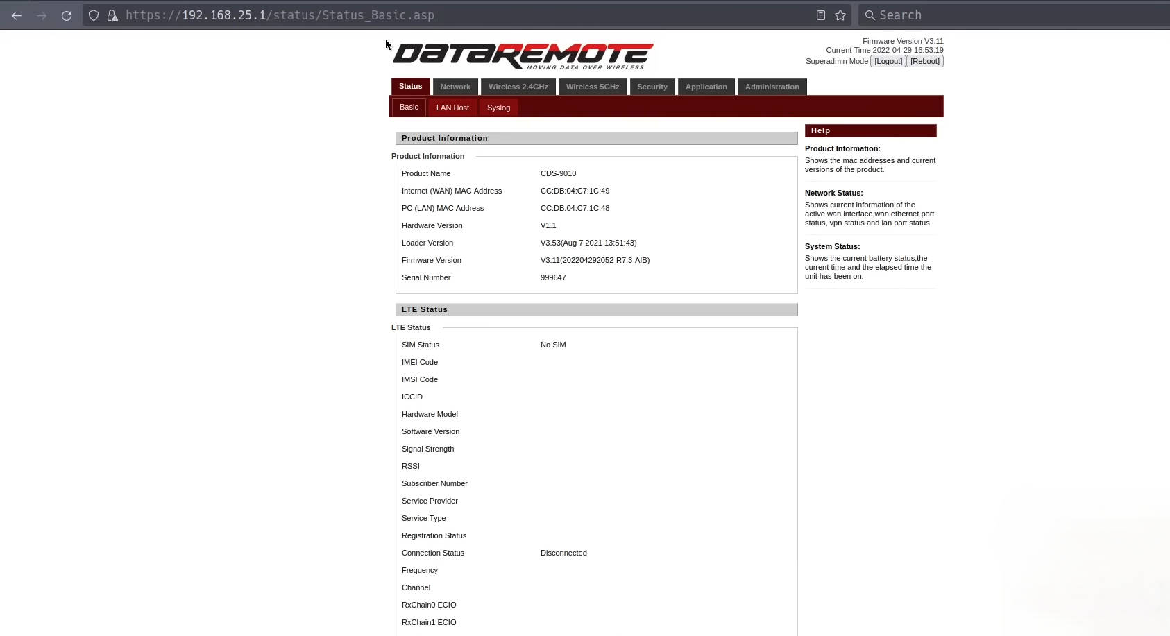
Logging into the Web Interface
With the extracted credentials (e.g., “super admin” and the corresponding password), attempt to log into the router’s web interface. This typically involves:
- Connecting to the Router: Use an Ethernet cable or connect to its Wi-Fi network.
- Accessing the Web Interface: Open a web browser and navigate to the router’s IP address, usually something like
192.168.25.1. - Entering Credentials: Use the extracted “super admin” credentials to log in.
Detailed Steps and Commands
Here’s a step-by-step breakdown of the process:
- Identify UART Pins:
- Use a multimeter to find ground pins.
- Probe for TX and RX pins by checking voltage fluctuations.
- Connect UART Cable:
- Ground: Rightmost pin.
- Receive (RX): Middle pin.
- Transmit (TX): Left pin.
- Setup Terminal Program:
- Use
picocomwith baud rate 115200:bashCopy codepicocom -b 115200 /dev/ttyUSB0
- Use
- Boot Device and Observe Output:
- Look for boot options and kernel command line.
- Note partition table addresses.
- Enter Bootloader:
- Reboot and press 4 during boot.
- Explore U-Boot commands:bashCopy code
help
- Read Flash Memory:
- Test
spi readcommand with small reads. - Read entire “config_back” partition:bashCopy code
spi read 0x1F00000 0x200000
- Test
- Extract and Parse Data:
- Use Python script to convert hex dump to binary:pythonCopy code
import sys def main(): in_fname = sys.argv[1] out_fname = sys.argv[2] with open(in_fname, 'r') as f_in, open(out_fname, 'wb') as f_out: for line in f_in: data = line.strip().split() for d in data: if len(d) == 1: d = '0' + d f_out.write(bytes.fromhex(d)) if __name__ == '__main__': main()
- Use Python script to convert hex dump to binary:pythonCopy code
- Analyze Binary Data:
- Use
stringscommand to find readable text:bashCopy codestrings out.bin | grep -i admin
- Use
- Login to Web Interface:
- Use extracted credentials to log in.
Successfully logging into the router with the “super admin” credentials, I regained control over the device. This process demonstrates the importance of understanding both hardware and software aspects when dealing with locked-down devices.
Final Thoughts
This comprehensive guide demonstrates the process of unlocking a locked-down AT&T LTE router. By understanding the hardware, leveraging UART connections, and using software tools to parse and analyze data, we can regain control over such devices. This approach not only empowers users but also highlights the importance of open and accessible technology.
Appendix: Troubleshooting and Tips
Common Issues and Solutions
- No Output on UART:
- Ensure the ground pin is correctly connected.
- Verify the baud rate settings.
- Check for loose connections or damaged cables.
- Bootloader Access Denied:
- Try different keys to interrupt the boot process.
- Check documentation for the specific router model.
- Invalid Credentials:
- Double-check the extracted data.
- Ensure no extra spaces or characters were copied.
Advanced Techniques
- JTAG Interface:
- For deeper hardware access, consider using JTAG (Joint Test Action Group) debugging. This requires more specialized equipment but offers greater control over the device.
- Custom Firmware:
- Consider installing custom firmware (e.g., OpenWRT) for enhanced features and control. This involves compiling and flashing the firmware, which can be risky.
- Reverse Engineering:
- Use reverse engineering tools like
binwalkandghidrato analyze the firmware and uncover hidden functionalities or vulnerabilities.
- Use reverse engineering tools like